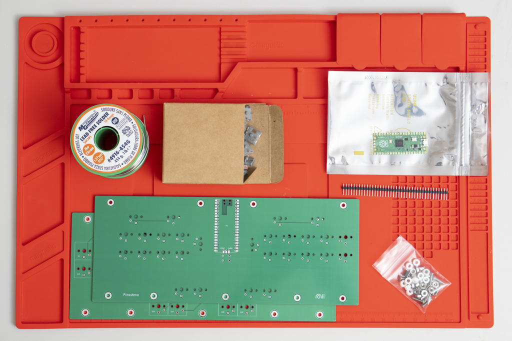
You’ll need a soldering iron, some solder (ideally lead-free*), and either a solder fume extractor or an open window to begin. You can see all the required parts here (with the keycaps and bumpers missing in this photo)
*Lead-free solder is recommended as the solder joints will be exposed.
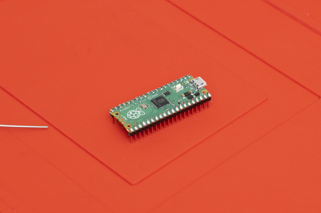
First, you’ll want to solder the headers to the Raspberry Pi Pico. (Advanced users may skip this step and solder the Pico directly onto top of the PCB)
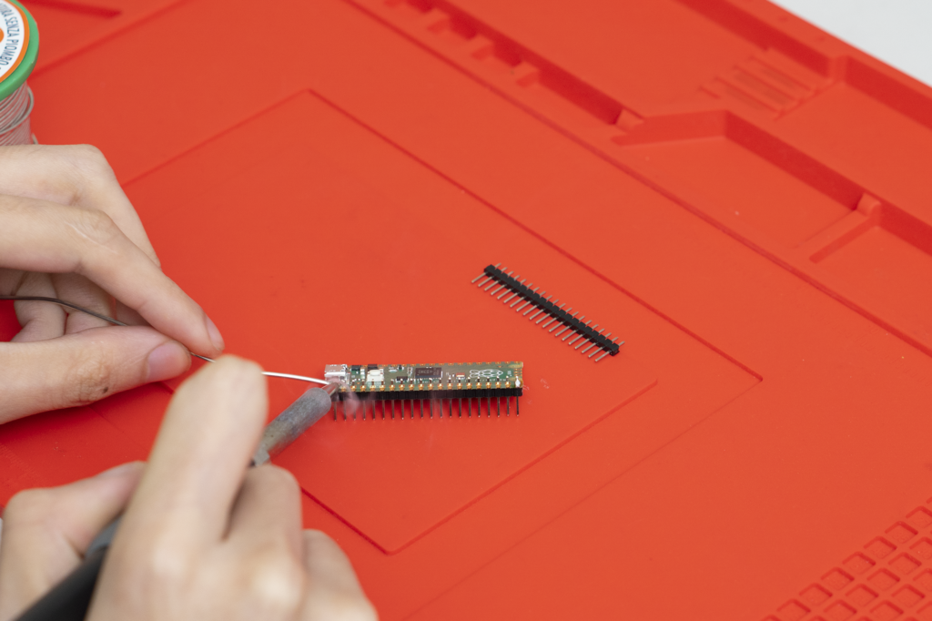
WARNING: Make sure to solder only one pin at first, and adjust the header until it’s straight! Crooked headers may make it difficult to put it into the keyboard in the next step.
If you’re having difficulties making the headers straight, you may try using the PCB to line up the headers for you.
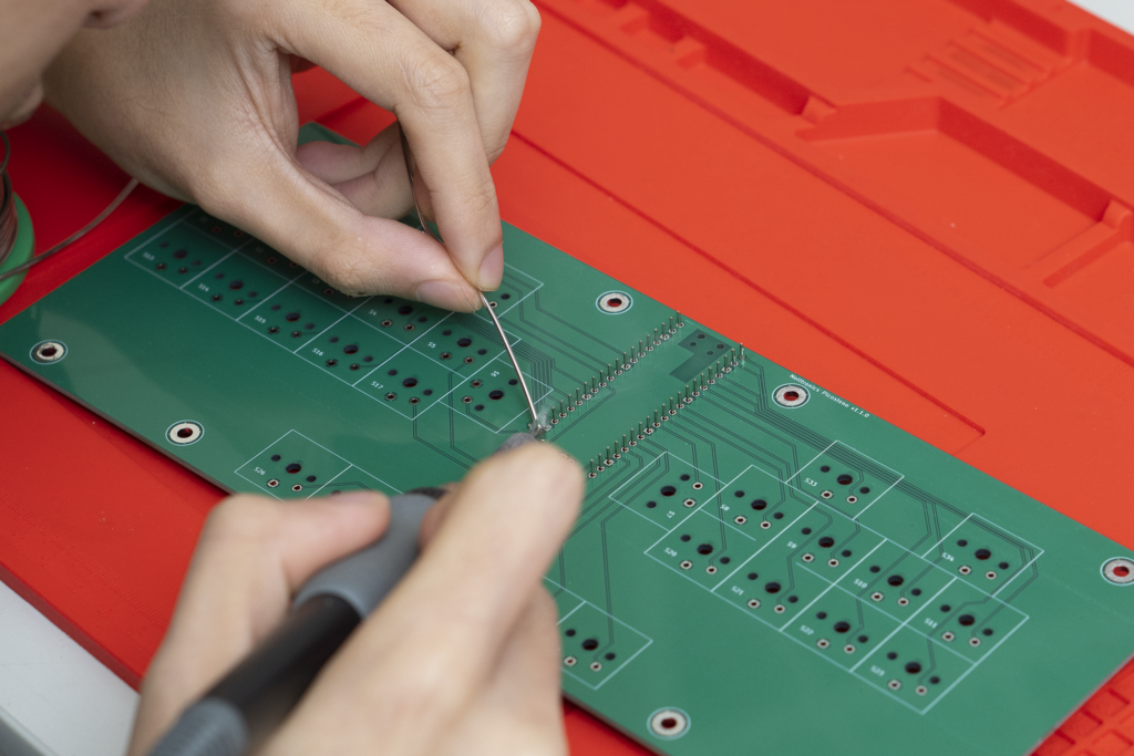
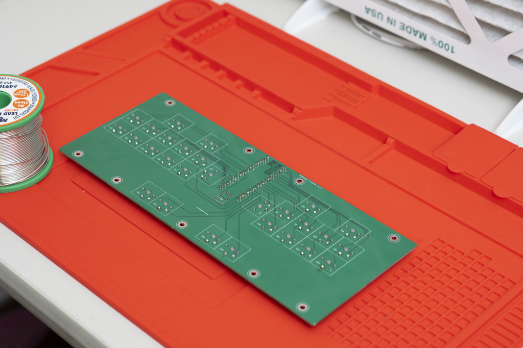
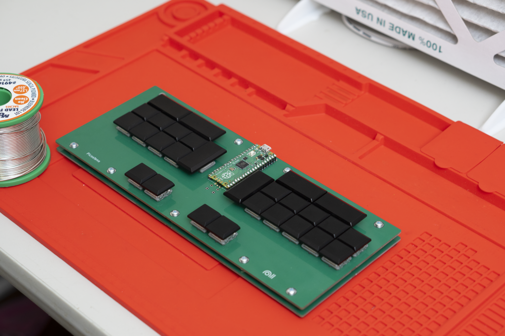
You’ll then want to place the Pico on the top of the PCB (the side with the noll logo), turn it upside down, and solder to the main board.
Next, push the keyswitches through the top of the PCB. They should snap in place – make sure they are pressed all the way down!
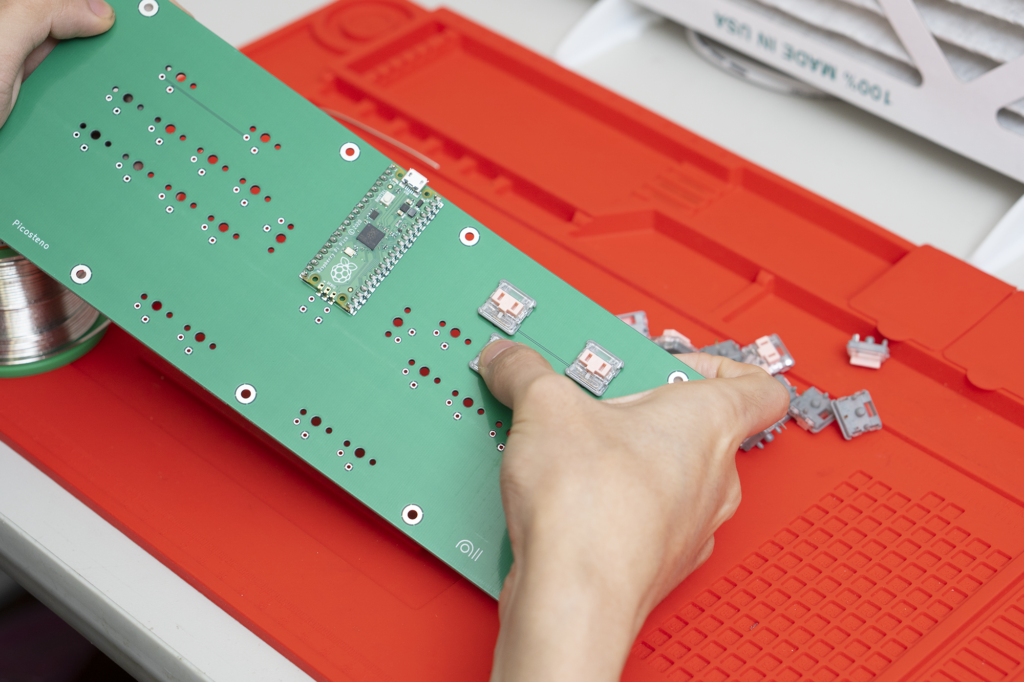
Once you have all of the switches pushed through, you can start soldering them on the back. Some of these pins are slightly harder than normal to solder (due to the ground plane), but they only need enough solder to make an electrical connection.
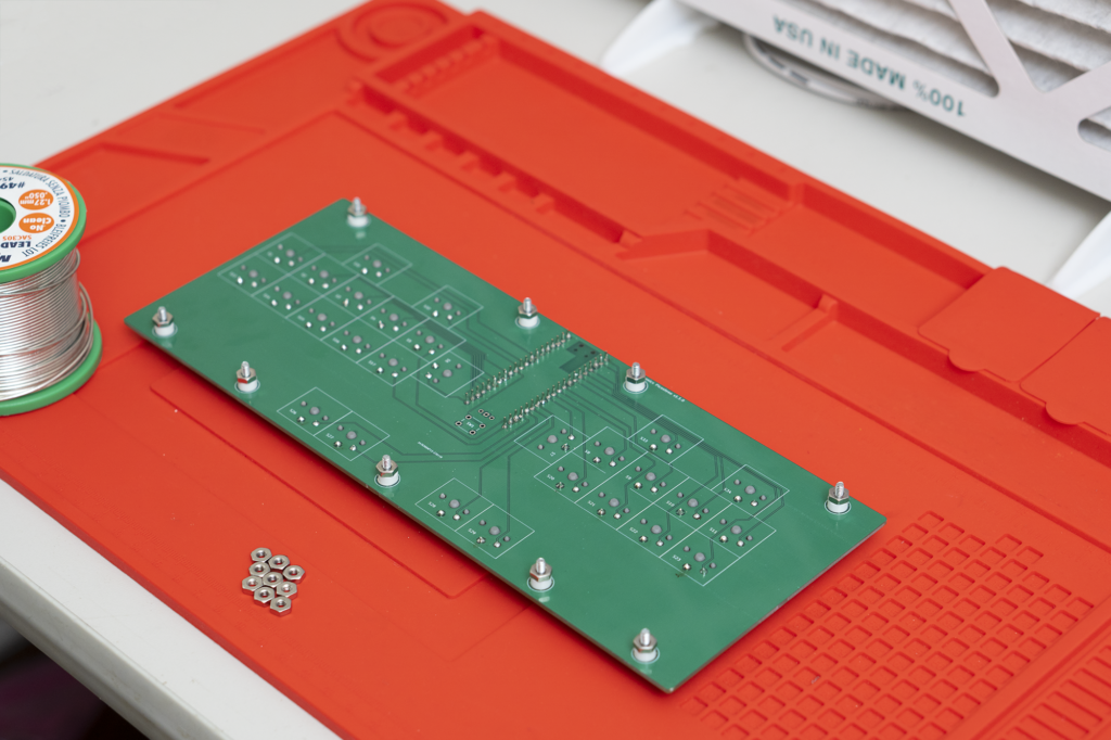
You can then prepare for assembling the backplate. Going one hole at a time, push the screw through the front of the PCB, add a spacer, and tighten a nut down onto it. This should hold the screw and spacer in place. Repeat this for all 9 holes.
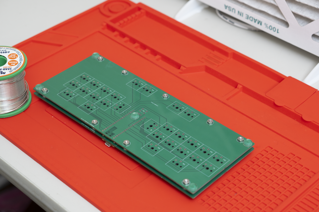
Then place the second PCB on top, securing it with the second set of nuts. You can also add the bumpers/feet to the bottom of the board at this time. You only need 4, it is recommended to add a fifth in the middle to prevent flexing.
You can then add the keycaps in the orientations shown below, completing the assembly process!
To finish, you’ll want to grab a USB-A to USB Micro-B cable and program your Picosteno, with either serial steno (Gemini PR) or NKRO firmware (or you can make your own!). https://github.com/nkotech/Picosteno-Firmware
Once you have your desired firmware, plug in the Pico while holding down the reset button and drag your firmware .uf2 file to the Pico USB device. Once you restart your Pico again, it should boot the firmware you just selected!
5 comments
Hi,
I wanted to 3d print a case for the picosteno. Do you have a 3d model of the picosteno that I could maybe use? Many thanks in advance
Sincerely,
jochanan
Hey Jochanan,
I don’t have any 3D models, but it’s 10″x6″ with standard 1.6mm FR4.
Best,
Nathan
Why is the file not saving in the raspberry pi?
I downloaded the utf2 file, and loaded it to the pico, it auto rebooted, but nothing happened. I saw the GitHub README sends us to QMK, but I am unclear why or if that is required for this. Can you clarify next steps? Thanks!
Hey ET,
If you picked serial steno (Gemini PR), you’ll need to set up Plover. If you’ve used the NKRO .uf2 file, it should start working like a normal keyboard immediately.
Best,
Nathan